Earth Notes: Expanding and Optimising Off-grid PV for Mid-winter (2016)
Updated 2026-07-13 10:18 GMT.By Damon Hart-Davis.

Goodbye To Lithium, for now

: LiFePO4 (LFP) battery removed and all PV input is now feeding to the ~400Ah gel lead-acid (LA) bank. The ~400Ah of lead-acid was itself integrated into the system . The 'test' is done after ~5 years! The observation is that the combination works well, but the complexity and partitioning of available energy may not be worthwhile.

In I also beefed up the lead-acid battery wiring with purpose-made cables (35mm^2 cable, length 25cm, lugs M8) between batteries as well as back to the controller, to minimise impedance and losses.
In I brought an additional direct (separately fused) connection from the battery bank to the house to be able to run heavy loads such as a car kettle or a small inverter.
In I installed an Enphase AC-coupled grid-tie LiFePO4/LFP Battery, so lithium is back in the house!
The Upgrade Plan

: the current plan is to put ~300W–500W of PV (~30Vmp) on the MPPT controller, and feed a nominal 12V set to a cheap ~20A PWM controller to get some value from any 12V panels retained. If it seems as if the current (15V/200W) MPPT is missing significant energy mid-winter then the 12V string may be moved back to it and a new 20A or 40A MPPT controller purchased for the 30Vmp strings. (Note: PWM 20A controller ~£25, MPPT ~£100.)
I quite fancy a 12V kettle instead of using the 3kW mains kettle; at ~30Wh per cup, maybe 180Wh/d. Rated 10A, so well within wiring ratings (~20A for 4mm^2), but given 15s@3kW, and this being 25x slower, ~6m to boil water for a cuppa (eg when the sun is out) seems plausible.
: LA battery getting first good solid uninterrupted absorption charge in a long while (11:10Z–14:20Z ie 3h @ 14.1V).
Here is the simplified system's schematic (PDF).

Mid-winter Blues
The big 5kWp+ grid-tied array on my roof only generates an average of about 1.5kWh/day mid-winter out of our ~5–6kWh/d demand. Were the big array south-facing rather than east and west, it would generate maybe double, though, realistically, I would not have that much roof facing south!
I have a very limited amount of south-facing wall relatively unobstructed, particularly from just before noon mid-winter when the sun-arc is small.
My target is to obtain ~500Wh or ~10% more of our daily electricity demand (also can be viewed as capturing one third more energy daily) in mid-winter by expanding the PV system somehow.
As a first step, the 'dump' (FTTC/router) network equipment load should be kept off-grid almost all the time (yellow hatching for this sample day below), in addition to the RPi2 and its always-off-grid few watts. (The unhatched part below is where it was light and the grid was not in 'red' a high carbon intensity time.)

Seeing the cheap (second-hand) PV (<40p/Wp Spring ) at Bimble Solar got me all excited, ie at something like one tenth what I have paid in the past, and made me think that a significant upgrade might be possible. (Note that Bimble's prices are good, but some new panels from elsewhere are not vastly higher, and for the cheap options I have to give up ~25% of the nominal generation capacity in the ~1.6m by 1m panel format.)
The south-facing wall space is occupied by a motley collection of 12V-nominal panels, not maximising energy collection ability, and the previous complex LFP and LA separate strings made such maximisation difficult while being kind to all the batteries, thus the reason to scrap the LFP element at least for now. There is maybe at best (without anything too ugly by my low standards) ~4m by ~1.5m usable space, though partially shaded, realistically a maximum of 500–700Wp might squeeze in there.
Also, when I had the last part of my grid-tie system put in I had these spare rails put up:
- rails from above, at edge of roof.
- vertical distance between the rails
- length of rails horizontally
So about 34cm/13.5" rail centre to rail centre and about 3m/10' long in an ~1m gap. And I have a bag of miscellaneous fixings/fastenings which may be Unirac Solarmount or very similar, in which case I seem to have 8x C clamps (1+7/16") for 33–36mm module thickness which accords with the 35mm-thick installed Sanyo HIT-215NHHE5 panels. As of 2016Q1 it might be possible to easily place 250Wp–600Wp up there.
So I could reasonably hope for 500Wp+ south facing (~500Wh/d mid-winter), and 300Wp shallow west-facing which could help when overcast and in afternoons.
The existing size of my grid-tie system (above G83 limits) and the presence of an export meter receiving FiT (Feed-in Tariff) means even the paperwork for connecting a small amount of extra PV, eg with microinverters, would probably be horrible.
The usable capacity of my (probably somewhat tired) 12V 400Ah gel lead-acid bank is well above the 500Wh/d target, and so it seems easier to capture that extra energy off-grid and find sensible ways to use it from there.
(Note that several sources suggest a maximum sustained charge rate for gel of about C/3, with a sensible charge controller to regulate it, which suggests that over 1kW/100A of PV could nominally be fed in to the bank.)
For example, it could be worth adding an inverter and transfer switch to take our mains lighting load off-grid when the battery SoC is decent, and the demand from our lighting is probably a similar amount.
Or, for example, making sure that the current loads (RPi+networking) are off-grid more of the time, which might be close to that 500Wp, with some opportunistic loads such as a 12V kettle to make use of some excess.
: the current plan implies preserving some of the existing panels (maybe ~160Wp) on a nominal 12V string, while putting two 260W panels on a nominal 30Vmp string (one on the roof could join them) in prime spots vertically mounted to minimise clutter and reclaim some patio! And maybe one more 260W panel could be roof mounted when I am feeling brave, though I may choose to wire it on as well as clamp it, given my inexperience! It looks as though the Unirac fixings I have would accommodate my current 100W 12V panel (NES40-5-100M, 40 cell, 20Vmp), lengthwise (probably not ideal for wind loading), and would not accommodate (in terms of panel thickness) the cheap 260W panels that I have been salivating over.
Test Mount with Al Brackets
: aluminium (wall-) mounting brackets arrived today, and I have tested them out with the ES-62T (62W, triple junction, 10kg) panel. I will need to up my game at least a little when mounting heavier (18kg) panels.
The easily-available unobstructed south-facing wall space sections are ~1320mm+ vertically (with some ground clearance), E to W, now are used as:
- a
- (obscured by bushes)
- b
- set back, 1150mm x 1320mm+, could accommodate 40W panel
- c
- 2.4W panel, tested, still functioning
- d
- (set back, tree in front, could maybe accommodate 20W amorphous horizontally)
- e
- 1120mm, currently has 40W panel + 20W mono at foot
- f
- set back, 1150mm, best insolation, currently has 100W + ~20W amorphous
- g
- ES-62T 60W panel now mounted on wall ~30cm from the ground
(f) + (e) are targeted for 250W+ panels (~1650mm x ~1000mm) as having the best (mid-winter) generation potential.
See panels in sections e/f/g below.
 with ES-62T on wall")
: some small potted plants have materialised below the 60W panel, hurrah!
Power Manager Snapshot
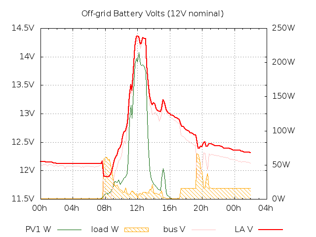
: I'm happy with estimation of battery SoC and handling of the optional/'dump' load (moving up to and extra ~300Wh/day off-grid), for example accounting for sag from discharge and lift during charging, so I have taken a code snapshot. I use the grid-tie output meter as one whopping great photocell, deciding when the battery should be being charged or not, and when I want to take the optional load off-grid to reduce night-time 'vampire' load (by a whole 13–14W)! (Graph for today...)
Also chatted today with builders about getting the 100W panel on the roof while we get some guttering issues fixed.
I'm writing this after sunset, with the server, Internet connection, laptop and desk light all off-grid (the laptop on its own battery).
Cabling for Two Strings
: significantly re-arranged and tidied (and shortened) wiring from panels, now not coming into the house at all, to make separate running of ~17Vmp and ~30Vmp strings to controllers near battery bank possible; currently the two circuits are combined at the controller and the '30Vmp' circuit is still being fed by the ES-62T panel.
: ordered some Schottky dual diodes (common cathode) 20A 100V to combine the two large panels in TO220AB and TO220FP packages (the FP, NTSJ20U100CTG, insulated tab, makes heatsink management easier). At worst the diodes might have to dissipate 10W (0.5Vf@20A for ~600W@30Vmp), but given for example a maximum 200W handled by the SS-MPPT-L a peak diode package dissipation of ~3W is more likely.
: have ordered a cheap 12V-nominal PWM solar controller to test. Bigger picture: given the very cloudy (climate-change 'blocking' jet-stream) weather and poor solar generation that we have had for weeks, along with a huge drop in (retail) PV prices per Wp, I'm more and more inclined to think that overspecing PV wrt to inverters/controllers and demand, to deliver useful output on non-sunny days, eg now and in the winter, is a generically sensible approach. (AKA 'inverter loading ratio', ILR.) Don't maximise mid-summer output: optimise for cloud and winter and dump excess happily and safely in the way that PV almost uniquely allows. That helps to provide something useful and zero-carbon year-round, with some opportunistic extra fossil-fuel (etc) avoidance in summer.
: hmm, wrong PWM controller arrived yesterday; hoping for next week. Meanwhile here is the proposed new schematic showing some of the 12V string moving to the new controller as an experiment to make sure that it still works reasonably well. With PWM as this new cheap 'temporary' controller is, there is some expected loss of available power into low batteries cf MPPT, eg in the morning where these panels on the east of the house seem to have been especially useful. Note that the LS2024RP is positive earth, so for example the -ve string lines cannot be parallelled.
: a LTC4151 might make a nice high-side power monitor for my off-grid solar panels with an input range 7V to 80V (so good even for 17V and 30Vmp panels) and an I2C interface ready to talk to a low-power MCU such as V0p2 REV11... One such V0p2 could listen to 8 such devices and transmit stats by radio, being powered from the string at the combiner box. The MCU could also drive 'ideal diode' (P)FETs for the key string panels to minimise losses, while lower-power 12V-nominal panels could maybe directly use (say) a LTC4358 or a AUIRF4905STRL P-channel MOSFET Transistor, 70A, 55V 'backwards'. Note that the saving is likely of the order of 200mV at ~10A, so 2W, so it is reasonable to ask if the <1% savings from a ~200W+ panel is worth the complexity and cost, beyond simply establishing that it works. Most pertinently at the moment, with an under-specified controller, are there real savings at low powers and light levels in winter when needed. Eg at 30V/30W/1A the savings may be more like 300mV and therefore 300mW at 10% generation (typical overcast winter) output, still at the 1% level.
Brave New World
: installed LS2024RP PWM 20A controller and moved ~100Wp of 12V-nominal solar to it including ~15Vmp 60W panel; battery type set to 2 (gel) circa; 10am–noon. There are a number of wiring inadequacies for the new controller that ought to be fixed, particularly two:
- Routing: the new cable run is split and is easy to knock while working on other things so longer (lug-terminated) cables should be installed.
- Bank attachment points: the battery connections for the new controller land on opposite corners of the bank, but the two other corners from the MPPT controller. This is a little controversial but is in the end expected to be a minority of the charge input and not a power drain point. So even if not sorted when the controller wiring is fixed, will probably not prove to be a problem.
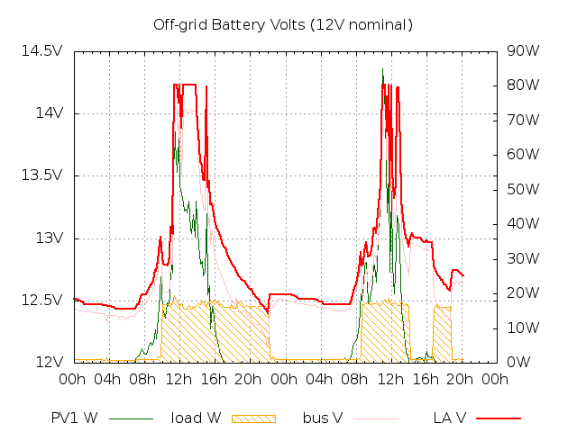
: day and month month graphs just-post-solstice as snapshots before major Wp addition, for comparison with post-upgrade and mid-winter...
Now also in possession of (ratchet) socket set including 8mm socket for panel fixings: finished off existing ES-62T (60W) panel mount.
: my first M4 connector with crimping to replace failed one in -ve lead of 100W panel that had been temporarily replaced with a connector block.
I am not at all convinced about the new connection; 4mm^2 wires pulled out even when re-crimped on smaller setting, so backed up with solder. Also, the M4 connector evidently did not mate properly the first time (no connection, detected by lack of forward bias at diode in junction box) so took it apart and removed stray solder blob and reassembled. Connection now apparently working but I will keep observing; this one may end up difficult to access on the roof so its integrity is particularly important.
: gah! When I finally get to order the panels only one is in stock which is a huge nuisance. This probably means I won't get 500Wp installed for the winter (unless I can a closely matching panel), and so the 100W panel may not make it up to the roof either... (May therefore end up with one string ~30Vmp 255W, and the nominal 12V (PWM) string 40+100+60+40W.)
: hurrah! Two substitute (Canadian Solar CS6P-255P) panels arrived, so now I just need the fixings etc to put them up and wire them in. I expect to upgrade the system in stages, eg putting up just one 255W panel first, alone feeding the SS-MPPT-15L, having moved all the residual 12V-nominal panels to the PWM string, retiring the 100W and a 20W panel at least temporarily.
CS6P-255P spec: 255Wp -0+5W, 30.2Vmp, 8.43Amp, 37.4Voc, 9Asc, module efficiency 15.85%, -0.34%Voc/C, normal operating temp 45C (+/-2), (NOCT 800W/m^2, 20C: 185W, 27.5Vmp), polycrystalline, 60 cells (6x10), 19kg, 1638 x 982 x 40mm (1.6m^2).
(Price was ~£100 per panel, ~£30 delivery.)
It's Huge
: (noon, 11:00Z) swapped over the strings and controllers: the brown/black pair that will be all the 12V nominal now feeds the PWM, the grey/green pair that will be the 30Vmp panels now feed the MPPT. The latter (grey/green) pair currently has the 60W (ES-62T) panel on it.
3pm (14:00Z) the first 255W CS panel is connected up (not yet cleaned) but the aluminium brackets don't seem to fit it, so it's just propped up against the wall for now (bah! again!). The CS panel is connected to the SS-MPPT-15L with no blocking diode, the 60W (ES-62T) panel has been moved to the 12V string, and the 100W+20W have been disconnected. A significant jump in battery voltage suggests that everything is working (on top of testing various points with a multimeter...).
(The CS panels are quite large in the flesh, taking up a whole garden wall panel!)
The positioning of the CS mounting holes along the edges is not as good for me as the JA panels as I have to mount this vertically on a wall and the furthest down from the 'top' edge might be above the top of the wall! So I am faced with possibly drilling new mounting holes, which worries me somewhat.
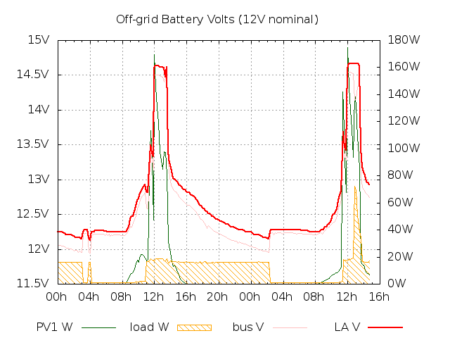
: some full sun on the new panel arrangement today, with the battery voltage shooting up to absorption, then sitting at float for several hours (second day of those shown), which is exactly the type of behaviour I am hoping for. (Plus the tweaked powermng behaviour allowing dumping to ride through brief dips into HIGH and OK.) The rise to absorption happened almost as soon as the sun came round the house to hit the new CS panel.
: a couple more days with interrupted sunshine, but the battery is clearly getting to something like float and getting a good charge.
: did first test hole in frame where it can work with the Al brackets. Somewhat slow with the hand (battery) drill, but not much drama. Had tape on drill bit and a ceramic tile and thick magazine behind hole to protect back of the panel if need be, but need wasn't.
: I'm doing the top holes 40cm from the 'top' of the panel, which will thus be 20cm below the top of the wall. I have bodged each of them in a different way, but basically made a pilot hole with a 4mm bit, and the 6.5mm bit makes a big enough hole for the bolt. There is quite a small 'good' area close enough to the edge for the Al bracket to work, but far enough for the nut not to foul the inside of the frame. In this case aiming for the middle of the ridged region seems about right. I'm putting the 'bottom' holes near the short edge to bear the weight as near the ground as possible (18cm from the short edge, midway between the existing holes). I am orienting the panel 'upside down' to kept the connector/wiring out of site at the base of the wall. My battery hand drill (~14Wh) ran down after making just the first two holes! As the drill bit breaks through it tends to catch and actually make the bit slip in the drill chuck, requiring some TLC to finish. Yes, for the four holes, "each bodged separately" as the TV ads might say, but done. Mounting on the wall is for another day...
: with the help of my kids, got the (second) CS panel mounted. More bodging, but it seems OK, with much of the load bearing directly down through a brick to the ground rather than being taken by the wall. Not convinced that it's electrically right, looking at the battery graph, even though it's an overcast day. May need TLC later. Did measure ~33Voc, and 29V when connected up, which is promising.
- a
- (obscured by bushes)
- b
- set back, 1150mm x 1320mm+, could accommodate 40W panel
- c
- 2.4W panel, tested, still functioning
- d
- (set back, tree in front, could maybe accommodate 20W amorphous horizontally)
- e
- 1120mm, currently has 40W panel + 20W mono at foot
- f
- CS6P-255P 255W panel now mounted on wall ~8cm from the ground
- g
- ES-62T 60W panel mounted on wall ~30cm from ground
(e) remains due the second 255W panel.

: making the extra holes in the second CS panel frame for mounting. Adjusting the hole positions slightly to try to hit mortar less. Adding extra mounting hole at bottom hoping to help load distribution, also more allowance for 'bad' mounting holes generally. Have taken down the 40W amorphous panel and removed the 20W 'floating' one.
: 2x255Wp Connected
: am: mounted and connected the second CS 255W panel.
- a
- (obscured by bushes)
- b
- set back, 1150mm x 1320mm+, could accommodate 40W panel
- c
- 2.4W panel, tested, still functioning
- d
- (set back, tree in front, could maybe accommodate 20W amorphous horizontally)
- e
- CS6P-255P 255W panel now mounted on wall
- f
- CS6P-255P 255W panel mounted on wall ~8cm from the ground
- g
- ES-62T 60W panel mounted on wall ~30cm from ground

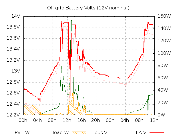
: some half-decent sunshine and the battery bank has probably had its best charge ever while in my custody! Note that the really steep rise around 11:00 UTC should actually come forwards in winter as the sun arc is smaller and the 255W panels will be in shadow from the house (to the east) for less or none of the day. We'll have to see...


: have lashed up MacBook Air via car (12V) universal 70W laptop regulator (Maplin N59AC) set to 15V and so I am back to being able to run my Mac off-grid, eg as a dump load. Note that the N59AC is not very efficient (~80%?). I happen to be able to charge my phone via the laptop this way too. Can aim to run server+Internet+light+MBA+phone off-grid all year this way.
: I will try to measure battery voltage at the battery
using the SS-MPPT-15L controller over MODBUS over RS232 so I will be ordering a
PC MeterBus Adapter. This should largely eliminate the effects of voltage drops in the supply cables when estimating SoC (leaving genuine sag from the battery bank itself). This should also allow measuring (some of) the power flow into the bank, and out to the loads. The are various solutions for having the RPi talk MODBUS to the SS-MPPT-15L, though I may prefer to keep everything in C for efficiency and use the LGPL
libmodbus
(see RPi build notes). Also see SolarNetwork in Java.
: with all the MODBUS data detail there are some nuggets. For example, coming up to solar noon and the battery in absorption with dwindling charge current I can see these values:
Sweep_Pmax (mW): 158264
Power_out (mW): 94457
which indicates that ~60W of power that could be used is not because the batteries are getting full and the ~40W of load that I have on at the moment is not enough to absorb the rest. (Why with both CS panels in direct sun the Pmax is not nearer the controller's 200W maximum, I don't yet understand.) Note that this is ignoring power/charging from the 12V-nominal string via the other (PWM) controller.
Oh, and as of yesterday the SS-MPPT-15L claimed that it had put a total of 202.5kWh of charge into the batteries over ~60,000h. And that keeping my battery bank in absorption takes ~60W, which would have been difficult to do with only ~140Wp of sun-facing panel at noon mid-winter. Float appears to soak up ~25–40W. The main charging window at the moment seems to be ~10:00–16:00Z.
: I have started collecting some cumulative off-grid stats. In particular cumulative generation (kWh) as reported by the SS-MPPT-15L. It seems evident that unlike the grid-tie PV which generates all that it can and exports it to the hungry grid, the off-grid system is only going to 'generate' at most the load plus any system and battery losses, ie providing more load may increase the reported generation.
: operating the battery DC breaker to the SS-MPPT-15L works, ie it produces a battery fault, but it does not result in the load being disconnected, so I am likely to replace the load fuse with a 20A breaker somewhere easy to access.
Also, measuring the voltage drop across the (20A MAXI) load fuse showed 15–25mA at an assumed ~2A draw, thus implying ~10mΩ rather than the expected ~3mΩ.
Inspection also shows that I could probably take another 1m (9mΩ) out of the cable run back to the house/load from the SS-MPPT-15L, so maybe ~20mΩ or 20% max that can be taken out of the load circuit. The run upstairs can be doubled up also to reduce losses to the Mac adapter which at ~70W peak (~5A) dwarfs the normal loads; maybe 100mV out of the ~500mV drop (~4% to ~3%) to it could be eliminated.
Some of this navel-gazing is because there has been quite a lot of power-LED flickering on the RPi, and it hung at 2am two days ago, which may be related. I adjusted some parameters (eg on the Gallery) to be less aggressive on power use but there is still some flickering. I may tighten up the supply (eg shorten leads, improve connections) from RPi all the way back to the solar controller to alleviate this issue and to reduce marginal losses.
: load fuse swapped out for circuit breaker and tested. No obvious change in load supply impedance to RPi observable.
: observation suggests that at least at this time of year output of primary panel array is 1/2 to 1/3 of that of grid-tie pro rata. For example, at at rather dark 13:12Z the grid-tie was generating 183W and as 13:16Z the primary array was generating 9.9W (presumably heavy cloud). Given relative array sizes maybe 18W would be expected. It will have to be seen how this effective efficacy ratio changes though the year (hopefully for the good in winter).
: further supply impedance notes. This pair of log entries:
2016/09/04T21:30:06Z AL 0 B1 12357 B2 -1 P 25048 BV 12103 ST OK D e A1P 0
2016/09/04T21:40:06Z AL 0 B1 12397 B2 -1 P 15695 BV 12243 ST OK D e A1P 0
suggests ~40mΩ internal battery impedance and a further 100mΩ towards the load at least at the Vbus sample point near the RPi. The latter figure confirms earlier values, the former is possibly higher than expected, though may be partly measurement granularity at the controller, and partly caused by 3 days' relatively poor charging (no float, little or no absorption time).
: checked output of the two CS 255W panels with multimeter in overcast conditions. Each separately delivering ~330mA Isc (~10W) and into the MPPT controller, so ~20W total vs ~560W from grid-tie system. So CS panels delivering ~4% of rated/peak, grid-tie ~11% of rated/peak, so confirming the 2x–3x ratio in actual:rated for vertical panels vs roof. May be extra good to get the 100W panel on the spare roof rails!
Possibly as a result of me fiddling with (checking) the CS panel connections, and/or because the battery is low enough to absorb the energy, the current into the battery just briefly hit the 15A limit (just over 200W):
2016/09/05T12:40:06Z AL 13007 B1 14148 B2 -1 P 26118 BV 13923 ST VH D h A1P 182754
2016/09/05T12:50:06Z AL 15000 B1 13926 B2 -1 P 23382 BV 14017 ST VH D h A1P 212347
2016/09/05T13:00:06Z AL 4984 B1 13349 B2 -1 P 24229 BV 13088 ST OK D r A1P 66268
: a few dull days and the system is starting to struggle, so have prioritised different calls on dump load; according to PVGIS this should be one of the better months!
2016/09/07T07:20:06Z AL 191 B1 12272 B2 -1 P 28705 BV 12093 ST L - L A1P 2326
But then all looks good with ~3 hours of 200W+ charging (~800Wh for the day), though not quite enough to hit float and thus 'FULL' status.

: typical total 'office' (evening, non-aggressive) off-grid load ~26W, for:
- FTTC Internet connection BT box + router (~13W)
- RPi server (~1W)
- Loop energy monitor (~2W)
- MacBook Air via laptop car power adapter (~6W)
- Desk lamp (~4W)
which implies consumption fairly close to the 500Wh/d generation target.
(: verified that mains load for Internet+Loop is zero when nominally powered as dump load, 13.7W from mains when not 'dumping', as measured with Maplin N67HH plug-in meter.)
2016/09/10T19:00:07Z AL 0 B1 12452 B2 -1 P 24705 BV 12234 ST OK D e A1P 0
2016/09/10T19:10:06Z AL 0 B1 12436 B2 -1 P 25395 BV 12234 ST OK D e A1P 0
2016/09/10T19:20:06Z AL 0 B1 12433 B2 -1 P 26135 BV 12225 ST OK D e A1P 0
2016/09/10T19:30:06Z AL 0 B1 12433 B2 -1 P 24991 BV 12225 ST OK D e A1P 0
2016/09/10T19:40:07Z AL 0 B1 12433 B2 -1 P 25351 BV 12215 ST OK D e A1P 0
2016/09/10T19:50:06Z AL 0 B1 12433 B2 -1 P 26073 BV 12234 ST OK D e A1P 0
Parallelled +ve connection (and generally improved) from power cupboard to desk to better support heavy recharge demand from laptop, and shortened power route to RPi in hope of reducing measured supply impedance and red power light blinking (but it is still blinking when RPi is working hard).
: voltage drop debugging: noting snippets of output from
ssmppt15l-modbus and powermng -v
under reasonable load (recharging my laptop at ~40W) there is as much as a 500mV from from battery to Vbus (at the RPi), though 246mV is shown in this snippet, of which 100mV is between battery and the load output of the SS-MPPT-15L.
Vb_f battery voltage slow (mV): 12522
Adc_vl_f load voltage (mV): 12421
Adc_ic_f battery charge current (mA): 510
Adc_il_f load current (mA): 3141
Load power (mW): 39332
SS-MPPT-15L Vb_f slow battery voltage (mV): 12443
SS-MPPT-15L Adc_il_f load current (mA): 2312
Load power (mW): 28769
Input flag DUMPING is unset.
SS-MPPT-15L Adc_ic_f battery charge current (mA): 404
External flag file /var/log/SunnyBeam/LOW.flag is absent.
ADC command 6a 80
ADC (6a 0) response 1300 (5 14 0)
Battery voltage 1 local (LA) 12197mV, 2 (Li) -1mV.
Supply drop B1 to BV 246mV; implied supply impedance 0.106401ohm.
Extending the (verbose-mode-only) calculation inside powermng to use load terminal voltage explicitly yields a slightly more comforting snippet, ie that a significant chunk of the voltage drop (possibly a quarter to a third) happens before my wiring loom, indeed before the controller's load terminals.
Verbose mode ($Id: powermng.cpp 15411 2016-09-11 08:40:19Z dhd $).
SS-MPPT-15L Vb_f slow battery voltage (mV): 12473
SS-MPPT-15L Adc_il_f load current (mA): 1472
Load power (mW): 18361
Input flag DUMPING is unset.
SS-MPPT-15L Adc_ic_f battery charge current (mA): 658
External flag file /var/log/SunnyBeam/LOW.flag is absent.
ADC command 6a 80
ADC (6a 0) response 1307 (5 1b 0)
Battery voltage 1 local (LA) 12262mV, 2 (Li) -1mV.
Supply drop B1 to BV 211mV; implied supply impedance 0.143342ohm.
Adc_vl_f load voltage (mV): 12397
Supply drop controller to BV 135mV; implied wiring impedance 0.091712ohm.
(It may be time to remove the dual Schottky feeding the RPi's 12V-to-5V step-down regulator, wasting a little power, and that may be adding to the apparent supply impedance.)
: two days in a row hitting FULL though interestingly float state at the controller can persist down to ~13.2V ie at a voltage that I consider merely 'OK'.
There seems no quick way to interrogate the controller to find when it last considered the battery full, ie in float; reading up to 32 days' historical data (of 32 bytes each) might be needed.
: some disappointments:
- even after hitting FULL, unable to sustain anything like 500Wh/d load after a couple of bad days; is the battery near death?
- somehow still unable to suppress dump oscillations completely yet.

2016/09/18T00:30:06Z AL 0 B1 12421 B2 -1 P 907 BV 12394 ST OK D e A1P 0
2016/09/18T00:40:06Z AL 0 B1 12320 B2 -1 P 16078 BV 12168 ST OK D T A1P 0
2016/09/18T00:50:06Z AL 0 B1 12302 B2 -1 P 16178 BV 12150 ST OK - m A1P 0
2016/09/18T01:00:07Z AL 0 B1 12397 B2 -1 P 881 BV 12365 ST OK - t A1P 0
2016/09/18T01:10:06Z AL 0 B1 12397 B2 -1 P 905 BV 12384 ST OK - t A1P 0
2016/09/18T01:20:06Z AL 0 B1 12397 B2 -1 P 905 BV 12384 ST OK - t A1P 0
2016/09/18T01:30:06Z AL 0 B1 12418 B2 -1 P 907 BV 12394 ST OK D e A1P 0
2016/09/18T01:40:06Z AL 0 B1 12314 B2 -1 P 16193 BV 12159 ST OK D T A1P 0
2016/09/18T01:50:06Z AL 0 B1 12296 B2 -1 P 16170 BV 12140 ST OK - m A1P 0
2016/09/18T02:00:06Z AL 0 B1 12397 B2 -1 P 905 BV 12347 ST OK - t A1P 0
2016/09/18T02:10:06Z AL 0 B1 12397 B2 -1 P 905 BV 12375 ST OK - t A1P 0
2016/09/18T02:20:06Z AL 0 B1 12397 B2 -1 P 905 BV 12375 ST OK - t A1P 0
2016/09/18T02:30:06Z AL 0 B1 12397 B2 -1 P 905 BV 12384 ST OK - e A1P 0
2016/09/18T02:40:06Z AL 0 B1 12406 B2 -1 P 906 BV 12384 ST OK - e A1P 0
2016/09/18T02:50:06Z AL 0 B1 12415 B2 -1 P 907 BV 12384 ST OK D e A1P 0
2016/09/18T03:00:06Z AL 0 B1 12311 B2 -1 P 16153 BV 12150 ST OK D T A1P 0
2016/09/18T03:10:06Z AL 0 B1 12281 B2 -1 P 16150 BV 12140 ST L - L A1P 0
2016/09/18T03:20:06Z AL 0 B1 12397 B2 -1 P 905 BV 12365 ST OK - t A1P 0
: continuing to hunt down supply drop from battery to load (and I'm now allowing for an internal impedance of ~90mΩ to damp down dump load oscillations for a 'soggy' run-down battery) I have added a little more calculation to powermng.cpp at the start, here shown with a fairly large load (laptop charging from ~empty + FTTC/router):
Verbose mode ($Id: powermng.cpp 15563 2016-09-24 23:11:42Z dhd $).
SS-MPPT-15L Vb_f slow battery voltage (mV): 12497
SS-MPPT-15L Adc_il_f load current (mA): 5847
Load power (mW): 73070
SS-MPPT-15L Adc_ic_f battery charge current (mA): 0
Input flag DUMPING is set.
System dumping for 414m.
LA/B1 dynamic threshold downward adjustment for load current 300mV.
ADC command 6a 80
ADC (6a 0) response 1263 (4 ef 0)
Battery voltage 1 local (LA) 11849mV.
Supply drop B1 to BV 648mV; implied supply impedance 0.110826ohm.
Adc_vl_f load voltage (mV): 12400
Supply drop B1 to controller load terminals 97mV; implied controller impedance
0.016590ohm.
Supply drop controller to BV 551mV; implied wiring impedance 0.094236ohm.
Removing ~5.5A of the load has the battery voltage jump back over 100mV, implying a battery-side impedance of ~20mΩ at the moment, so a tally of impedance to the RPi 12V power intake measurement point is:
- ~20mΩ battery and breaker and wiring to controller
- ~20mΩ controller (battery terminals to load terminals)
- ~90mΩ breaker and wiring downstream of controller
though note that 4mm^2 is down as 9.22mΩ/m (two way) so ~6m from controller to RPi should be ~55mΩ. The 20A DC breakers on either side of the controller should be similar to a MAXI 20A fuse, ie ~3mΩ each, So still a mystery 30mΩ between controller and RPi!
(Looking again at the main wiring from controller to RPi, I think that 6m is a better estimate than my previous 4m value. possibly ~1m could be removed to save ~10mΩ.)
To put this in context, at a minimum RPi-only draw of ~1W (~80mA), ignoring draw by the controllers, the wiring losses etc from battery to RPi (@~130mΩ) are ~10mV (~0.1%); the loss from the redundant Schottky diodes just upstream of the RPi is probably ~350mV (ie ~3%) so possibly worth fixing. For the RPi+networking load of ~1.3A, wiring losses from the controller are ~120mV or ~1% at most. I can shorten the wiring loom or parallel up the unused cores to save ~30mΩ, but it is not a priority for now.
Note that the laptop power adapter no longer 'screams' under heavy load (~60W); doubling the wiring run to it from downstairs seems to have been worthwhile.
This snippet, putting the laptop on to charge from near empty, suggests 40mΩ for B1 internal resistance + breaker + cable to controller, ie ~5A (~60W) increase in load caused a sag of ~200mV:
2016/09/25T07:40:06Z AL 278 B1 12439 B2 -1 P 16358 BV 12300 ST OK D e A1P 3473
2016/09/25T07:50:06Z AL 382 B1 12244 B2 -1 P 74309 BV 11605 ST OK - e A1P 4636
The sag/drop to BV, the RPi 12V input, was ~700mV, implying 140mΩ total supply impedance to BV.
Also, with the aim of making full and more precise use of my available storage during the (cold) winter, I have attempted to fold in some code support for temperature compensation of voltage set-points at the low end in particular, and so I am also logging/recording the battery temperature (using the Morningstar remote probe attached to the battery). It will be interesting to compare that to general exterior temperatures, eg observe time lags. I have set an initial base temperature of 20°C and 24mV/°C discharge, ie the thresholds for SoC levels drop with temperature, as per Victron advice, though I note that the SS-MPPT-15L uses 25°C and 30mV/°C for adjusting its setpoints. The slope is likely more critical (given that I am happy with my current setpoints today at 20°C) but I may adopt the Morningstar slope later.
: maybe dump oscillations are now damped...

: yesterday ~1/2 kWh was generated by the main off-grid array, with a rolling average of ~1/3 kWh/d, so below target.
: "Use it or loose it" experiment and data sample.
: (17:20Z) system measured under reasonably heavy load, after dark:
Verbose mode ($Id: powermng.cpp 15710 2016-10-13 07:35:43Z dhd $).
SS-MPPT-15L Vb_f slow battery voltage (mV): 12281
SS-MPPT-15L Adc_il_f load current (mA): 5781
Load power (mW): 70997
Input flag DUMPING is set.
System dumping for 475m.
SS-MPPT-15L Adc_ic_f battery charge current (mA): 0
SS-MPPT-15L T_batt (C): 13, discharge compensation -210mV.
LA/B1 dynamic threshold adjustment for load current -300mV.
ADC command 6a 80
ADC (6a 0) response 1246 (4 de 0)
Battery voltage 1 local (LA) 11690mV.
Supply drop B1 to BV 591mV; implied supply impedance 102mohm.
Adc_vl_f load voltage (mV): 12208
Supply drop B1 to controller load terminals 73mV; implied controller impedance 12mohm.
Supply drop controller to BV 518mV; implied wiring impedance 89mohm.
: am: having to resort to charging my MacBook from mains rather than the off-grid system for first time since the new panels went up, given the laptop near empty and the LA battery 'Low' this morning after poor insolation (particularly fog and thick cloud yesterday, fog this morning). The SS-MPPT-15L indicator was amber yesterday, so I'd like to let the battery get some charge and get back to green (13.1V).
The last few days' main-array generation reported by the SS-MPPT-15L in 0.1kWh units (sub-50Wh yesterday for example):
2016-10-25 0.2 0.310526
2016-10-26 0.2 0.3
2016-10-27 0.5 0.3
2016-10-28 0.3 0.29375
2016-10-29 0 0.293333
: pm: mounted the 40W amorphous panel in bay b as planned to try to catch some/more energy mid-morning outside of summer months:
- a
- (obscured by bushes)
- b
- Maplin N27JL 40W amorphous panel mounted on wall ~50cm from ground
- c
- 2.4W panel, tested, still functioning
- d
- (set back, tree in front, could maybe accommodate 20W amorphous horizontally)
- e
- CS6P-255P 255W panel now mounted on wall
- f
- CS6P-255P 255W panel mounted on wall ~8cm from the ground
- g
- ES-62T 60W panel mounted on wall ~30cm from ground
The 40W panel was connected to the secondary string/array and was live ~14:30Z, and the secondary string is now ~140Wp.
: it appears that imports from the grid dropped about 6kWh this month compared to last October (106kWh vs 112kWh) according to Pilio/sMeasure/iMeasure though gross consumption (I+G-E) has gone up up 6kWh while off-grid generation from the primary array was a similar ~10kWh. Not all movement of consumption off-grid happens at a time when it reduces imports, eg when the grid-tie is already causing net-exports. Taking load off-grid at night does directly save grid imports.
Note that ~2.5h of weak sunshine through haze where grid-tie hit ~1/3rd of max (thus maybe equivalent to nominal 1h/d full sun expected mid-winter) was able to hit the full ~0.5kWh/d target charging at a solid ~200W. This was probably only possible because the PV is overspecified >2x.
: sag with the fixed (networking equipment) dump load has risen to ~120mV with the LA battery at ~8°C, so rather than keep manually adjusting the constant in the code that allows for impedance-based sag, I have added temperature compensation, initially at -7mΩ/C, ascertained empirically by raising it from ~4 until dump oscillation stopped.
: with outside temperatures near freezing and the battery ~6°C, I have raised the impedance temperature compensation to -13mΩ/C, as oscillations have been nudging in again.
: raised the impedance temperature compensation to -15mΩ/C to help damp oscillations seen with battery at 2°C.
: so far the goal of 0.5kWh/d off-grid is being missed hugely; the running average is more like 0.2kWh/d now, close to winter solstice. Daily output is hugely variable, with more than an order of magnitude difference between today and yesterday (~0.4kWh/d).
: a respectable generation of ~400Wh today, with the running average a little over 110Wh/d to yesterday.
: there definitely seems to be an element of 'use it or lose it' when the battery is cold and thus unable to absorb much charge. Shortly after noon, adding a ~50W load from my MacBook saw primary generation jump by a very similar amount, with the battery voltage remaining flat at a little over 14.5V (battery at 3°C).
500Wh/d Winter Target Not Met
Possibly for a number of reasons including reduced battery bank capacity when cold (and it has been the coldest winter for a few years), the target for 500Wh/d of generation from the two large panels has not been met by a long chalk with a low around the solstice of more like 150Wh/d.

Code snapshot taken with what appear to be decent temperature compensation values.
: battery hit 'full' two days in a row according to the Morningstar controller; notice the float 'shoulder' on the right for the second day.
: interesting misbehaviour of 'dump' which went off and didn't come back on
until I forced it back on by manually setting the DUMPING flag. Possibly the charging current was not a high enough multiple of the expected dump load current because the battery was near full and getting enough current from the other charge controller...
: I think that I could have the temperature coefficients rather wrong; the internal impedance etc is computed so high at 30°C that the battery could not dump unless on fire or something!
# powermng -nv
Verbose mode ($Id: powermng.cpp 15983 2017-01-19 17:11:57Z dhd $).
SS-MPPT-15L Vb_f slow battery voltage (mV): 13297
SS-MPPT-15L Adc_il_f load current (mA): 747
Load power (mW): 9933
Input flag DUMPING is unset.
SS-MPPT-15L Adc_ic_f battery charge current (mA): 1443
External flag file /var/log/SunnyBeam/LOW.flag is absent.
SS-MPPT-15L T_batt (C): 31, discharge compensation 0mV.
Estimated LA battery impedance: 65440mohm.
Estimated actual battery sag from load (mV): 0mV.
LA/B1 dynamic threshold adjustment for load current 0mV.
B1 and wiring dump load sag allowances 18947mV, 194mV.
ADC command 6a 80
ADC (6a 0) response 1397 (5 75 0)
Battery voltage 1 local (LA) 13107mV.
Supply drop B1 to BV 190mV; implied supply impedance 254mohm.
Adc_vl_f load voltage (mV): 13279
Supply drop B1 to controller load terminals 18mV; implied controller impedance
24mohm.
Supply drop controller to BV 172mV; implied wiring impedance 230mohm.
Input flag EXTERNAL_BATTERY_NOTVHIGH is set.
Input flag FORECAST_PV_GEN_GOOD is set.
Battery voltage 1 'very low' threshold 12100mV.
Flag EXTERNAL_BATTERY_VLOW is unset.
Battery voltage 1 'low' threshold 12300mV.
Flag EXTERNAL_BATTERY_LOW is unset.
Battery voltage 1 dump margin threshold 31297mV.
Battery voltage 1 'not high' threshold 13450mV.
Flag EXTERNAL_BATTERY_NOTHIGH is set.
Flag EXTERNAL_BATTERY_HIGH is unset.
Battery voltage 1 'very high' threshold 13600mV.
Flag EXTERNAL_BATTERY_NOTVHIGH is set.
Flag EXTERNAL_BATTERY_VHIGH is unset.
Flag EXTERNAL_BATTERY_NOTFULL is set.
Flag EXTERNAL_BATTERY_FULL is unset.
Setting up_threshold to 60%
Input flag NODUMP is unset.
Insufficient margin to dump, threshold 31297.
Flag DUMPING is unset.
Flag DUMPINGEND is set.
SS-MPPT-15L Power_out A1P (mW) 19236.
LASTDATA: 2017/06/20T16:58:37Z AL 1443 B1 13297 B2 -1 P 9933 BV 13107 ST OK - m
A1P 19236 B1T 31
In particular this is the impossible number preventing dumping:
Insufficient margin to dump, threshold 31297.
And this looked suspiciously like an overflow (eg of uint16_t) but turned out to be a sightly more complex signed/unsigned/underflow issue:
Estimated LA battery impedance: 65440mohm.
Here is the relevant patch/diff:
===================================================================
--- powermng.cpp        (revision 17846)
+++ powermng.cpp        (working copy)
@@ -315,7 +315,8 @@
 static constexpr uint16_t sagLAmVperADumpCorr = 80;
 // Increase in sag per C below base temperature (eg 20C).
 static constexpr uint16_t sagLAmVperAperCDumpCorr = 16;
-constexpr uint16_t sagLADumpCorr(const int tempC) { return(sagLAmVperADumpCorr + sagLAmVperAperCDumpCorr*(20-tempC)); }
+constexpr uint16_t sagLADumpCorr(const int tempC)
+    { return(uint16_t(MAX(0, int(sagLAmVperADumpCorr) + int(sagLAmVperAperCDumpCorr)*(20-tempC)))); }
 // Allowance mV/A for supply drop due to controller+wiring impedance (mohm).
 static constexpr uint16_t sagWiringmVperADumpCorr = 150;
Thresholds Up
: to buy or not to buy? Do I need to splash out a grand?
The lead-acid bank's capacity is looking increasingly dire, and I asked in this thread on Fieldlines for ideas on a possible replacement bank.
A suggestion from clockmanFRA, and that I have vaguely considered in the past to help protect against sustained over-discharge in the winter, is simply to limit the depth of discharge (DoD). He suggests 10% DoD max with leisure batteries as a radical approach.
I won't do anything quite that drastic yet, but I am right now creating 'conservative' / 'low-DoD' settings for my bank voltages to see if that keeps the bank healthier. If I'm not trying to power external loads, keeping the RPi running should be easy. I may this more dynamic by greatly raising the thresholds in the absence of (say) forecast sunshine, or recently hitting 'full'.
The key adjusted lines (with LESS_DoD = true) are:
static constexpr int BATT1_THR_L_mV  = LESS_DoD ? 12600 : 12300;
static constexpr int BATT1_THR_VL_mV = LESS_DoD ? 12450 : 12100;
Installing the updated code has pushed my bank from being in an apparently 'OK' state to 'VERY LOW', and the system should draw much less juice from it until the SoC rises significantly.
This will greatly reduce the nominal capacity of the bank, though if it reduces sulphation of this bank or its replacement, maybe less so than it appears on the surface.
I'm also increasing to nominally ~2 days' use (~50mV if the battery were at its original capacity, so probably back to more like 1 day again in reality) the extra margin to add in for a poor forecast tomorrow. This extra margin is also used if it has been more than a day since the battery last reached VHIGH. I may also extend that to "if not FULL for a week"; currently FULL has not been reached since the machine was last rebooted about a month ago! One to watch with the new thresholds...
See the new scheme graphically, along with mean temperatures and available sunshine dropping.
Lower
: as expected, especially on dull days, I'm seeing relatively little dumping, with a much-improved minimum/overnight voltage.
I'm trying a slightly-less conservative set of thresholds, that should still avoid sulphation, but should expose a bit more of the battery capacity (100mV ~ 10% of capacity):
// LOW threshold: ~85%/100% SoC un/loaded.
static constexpr int BATT1_THR_L_mV  = LESS_DoD ? 12500 : 12300;
// VERY LOW threshold: ~75%/90% SoC un/loaded, with some line voltage drop.
static constexpr int BATT1_THR_VL_mV = LESS_DoD ? 12425 : 12100;
Lower Bruce, Lower!
: according to Battery University, sulphation seems to be a problem at more like 12.3V than 12.4V. Note also that the VLOW threshold is a hard stop on dumping, with no further allowances for battery impedance, etc, so bringing VLOW down a bit further (but keeping VLOW and LOW well above sulphation voltages) may allow dumping to continue once started to make decent use of capacity, while allowing a return to a decent higher voltage and SoC. The issue is if it possible to avoid dumping for a long time, keeping the SoC too low too long for safety...
// LOW threshold: (LESS_DoD) ~85%/100% SoC un/loaded.
static constexpr int BATT1_THR_L_mV  = LESS_DoD ? 12500 : 12300;
// VERY LOW threshold: (LESS_DoD) ~70%/85% SoC un/loaded.
static constexpr int BATT1_THR_VL_mV = LESS_DoD ? 12350 : 12100;
These threshold values, compared to those of a few days ago, may allow use of another 10% of raw/nameplate capacity (ie 20% of usable capacity) while guarding against further premature damage and capacity loss.
See the slightly lower overnight resting voltage.
Who Guards the Guards?
: I was concerned that the powermng program itself might be starting to eat significant CPU time and thus energy, since it is now fiddling with increasing numbers of (eg) governor parameters and thus incurring extra context switches, etc. But actual user and system CPU time is still very low, maybe working out as 10ms every 10m run.
# time /usr/local/bin/powermng -n
real    0m0.940s
user    0m0.010s
sys     0m0.000s
# time /usr/local/bin/powermng -n
real    0m0.940s
user    0m0.020s
sys     0m0.000s
# time /usr/local/bin/powermng -n
real    0m0.938s
user    0m0.010s
sys     0m0.000s
More Explicit
: a number of places in the code have been slanted to aggressively try to move the (dump) load off-grid, eg to help reduce the house's demand from the grid overnight and whenever the grid-tie system cannot cover house loads.
With LESS_DoD true I now tweak compile-time thresholds so as to be less keen to prop up the grid, and instead prioritise preserving battery life (and reserve to run the RPi).
However, when the grid needs some TLC (eg peak demand, peak carbon-intensity), this system will still try to help by covering maybe one-quarter-billionth of GB demand!
: I have now separated the externally driven dump demand into high-priority items (high grid demand or carbon intensity), and the rest, and only allow the latter group to trigger dumping (when
LESS_DoD is true) when the battery has gained significant net charge during the day. The aim is to promote battery health and an increasing SoC until the battery is hitting FULL. (I may need to add specific code to allow the low-priority dumping when recently FULL.) I may want to add the "only when gained charge on the day" condition to other places too.
You can see dumping stopping early and then correctly resuming later during high grid carbon intensity. The early stop was caused by heavily overcast orange skies caused by dust and smoke brought in from the south by a hurricane while it was monstering Ireland.
There are now two new status code letters in the log: 'N' for not enough net charging in the day for anything other than high-priority grid support, and 'E' for those high-priority factors such as peak grid demand or carbon intensity.
: a significant semantic upheaval is now under test:
VHIGH now indicates passing the specified voltage threshold
and reaching absorption (or float) which implies a thorough (and efficient) charge. The 'H' timed start to dump is now upgraded to 'A' indicating having reached absorption (and been HIGH for long enough). 'N' now means that low-priority dumping is blocked because there has Not been a recent decent charge likely to avoid sulphation amongst other limits to DoD. A recent VHIGH
no longer just implies a brief spike from the big panels, but instead leans on the charge controller to be an indication of a decent SoC, ie out of 'bulk' phase.
: back to "use it or lose it": in this case Sweep_Pmax
greater than Power_out and Load power suggests that the battery cannot accept (much more) charge and the panels connected via the PWM controller are providing ~6W. This does strongly imply that the dump load should make use of the energy that is otherwise being wasted.
Vb_f battery voltage slow (mV): 14271
Adc_vl_f load voltage (mV): 14200
Adc_ic_f battery charge current (mA): 747
Adc_il_f load current (mA): 1179
Load power (mW): 16826
Adc_va_f array voltage (mV): 35044
Sweep_Vmp (mV): 26636
Sweep_Voc (mV): 32117
Sweep_Pmax (mW): 36554
Power_out (mW): 10615
kWhc (kWh*10): 3342
charge_state: 6
Ahc_daily (mAh): 8400
Ahl_daily (mAh): 5300
T_batt (C): 16
: FULL (since Wed Feb 7 13:20:08). Hurrah!
2018/02/07T13:20:07Z AL 2008 B1 14332 B2 -1 P 17801 BV 14045 ST F D F A1P 28869 B1T 4
: Cold! More 'FULL' episodes over recent days, but with temperatures steadily falling (to 0°C at the battery bank, -2.5°C in the porch early this morning) the voltage margin 'm' at night is not enough to avoid dropping into VLOW just before dawn. So maybe set the temperature-adjusted margin to reflect the coldest forecast temperate during next 12–24h (or until dawn if the sun is down) to avoid this?
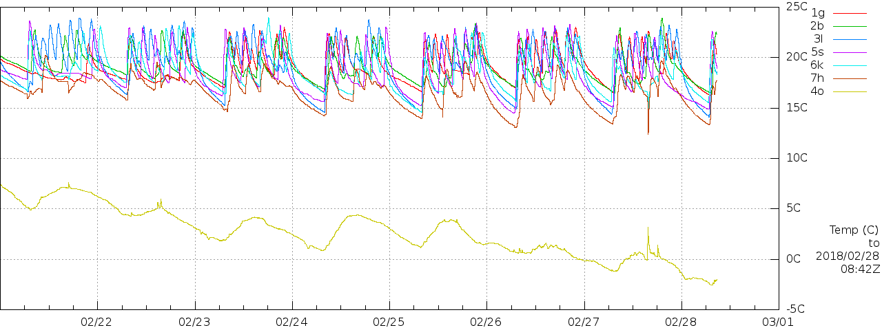
: Colder! A bit colder outside and the battery bank several days at 0°C. I don't know if the battery temperature sensor read remotely this way can show negative values, so the battery may have been colder than shown.
: looking at the numbers indicates that letting the battery get FULL costs ~30Wh of lost energy (presumably as heat of recombination). This 'loss' is the difference between generation (from PV) and load. So about boiling the water for a small mug of tea or coffee... (There could be other factors at play, and this ignores any contribution from the secondary PWM charger and panels.)
Kettle and Immersion
To test the "use it or lose it" hypothesis further, I ordered a 12V kettle and an in-cup immersion heater, both maybe ~150W, giving me two orders of magnitude of loads from RPi through networking gear to kettle. I'll have to be careful that the kettle load doesn't hurt the solar controller nor crash the RPi by yanking the supply down too far. The controller maximum load is 15A, thus ~180W. It could struggle with simultaneously powering the networking gear and kettle. The goods arrived .
Brief tests of the loads direct to battery, with bright sunshine on the main panels, to measure actual power consumption of the devices, suggest that they would only just just squeak in on the controller's 15A max load (~180W), and that would be slightly dodgy if the network dump gear was engaged. Note that the battery was absorbing ~10W throughout these tests.
Immersion heater direct to battery: cable getting quite warm, no fuse! Computed power ~130W, 8m to 'hot', thus ~19Wh, full log:
2017/10/27T12:05:01Z AL 10961 B1 14310 B2 -1 P 17673 BV 14082 ST VH D V A1P 156799 B1T 15
2017/10/27T12:05:07Z AL 10995 B1 14310 B2 -1 P 17602 BV 14092 ST VH D V A1P 157282 B1T 15
...
2017/10/27T12:05:23Z AL 11024 B1 14310 B2 -1 P 18088 BV 14073 ST VH D V A1P 157660 B1T 15
2017/10/27T12:05:59Z AL 11082 B1 14310 B2 -1 P 17573 BV 14092 ST VH D V A1P 158566 B1T 15
2017/10/27T12:06:04Z AL 11082 B1 14310 B2 -1 P 17845 BV 14082 ST VH D V A1P 158520 B1T 15
Kettle, much thicker leads not getting hot, fused lighter plug, but overheating my lash-up, ~150W:
2017/10/27T12:12:07Z AL 2097 B1 14310 B2 -1 P 17945 BV 13979 ST VH D V A1P 29926 B1T 15
2017/10/27T12:12:12Z AL 10374 B1 14307 B2 -1 P 18185 BV 14045 ST VH D V A1P 179145 B1T 15
2017/10/27T12:12:17Z AL 12608 B1 14307 B2 -1 P 17498 BV 14092 ST VH D V A1P 180413 B1T 15
2017/10/27T12:12:23Z AL 12608 B1 14307 B2 -1 P 17527 BV 14064 ST VH D V A1P 180413 B1T 15
..
2017/10/27T12:13:10Z AL 12691 B1 14310 B2 -1 P 17115 BV 14092 ST VH D V A1P 181591 B1T 15
2017/10/27T12:13:15Z AL 12582 B1 14307 B2 -1 P 16911 BV 14073 ST VH D V A1P 179991 B1T 15
2017/10/27T12:13:20Z AL 12582 B1 14310 B2 -1 P 16843 BV 14082 ST VH D V A1P 179991 B1T 15
In any case this shows that the panels were happy to supply enough for a cup of tea with the sun out, and the batteries were simply not absorbing what was available.
I have a spare pair of meaty conductors from the batteries to the kitchen plus a spare 20A MAXI fuse, so I may well wire them in to get an off-grid cuppa facility.
It seems fairly clear that, as right now, I should probably power my laptop off-grid when the sun is bright on on my 550W of panels; it's energy otherwise going to waste!
A subsequent test of the kettle (again 200ml water, a better direct connection to the battery bank) had the water getting hottish after about 8 minutes and just boiling in about 20m. Quite a lot of this energy goes into making the kettle itself warm! Full log.
Direct Feed
: instead of doing other things I ought, I have started wiring in the direct 12V feed to the house from the batteries, bypassing the controller. The -ve/0V/GND rail is electrically common with the output of the controller (GND is straight through). It could possibly be commoned at the house end to reduce cable losses from normal loads by 25%, at the risk of setting up unexpected circulation currents from a non-star topology. The +ve/12V will be separately fused (20A MAXI) as near the battery as possible.
A test cup of coffee was made with the kettle direct to the battery, purely for engineering purposes. (Instant) coffee was deemed more efficient than tea in this instance as the water need not come fully to the boil for an acceptable result. The energy used is revealed partly by an imbalance between generation so far today (~167Wh) and controller-supplied load (~53Wh) at 13:00.
This will allow running intermittent loads up to ~200W in the house, such as the 12V kettle, or immersion heater, or small car space heater, or even in future a small inverter (such as I already have) in case of power cut. For sustained load I would need to improve connections and wiring.
I note that in the house I am measuring ~40mV (the meter claims ~37mV) between the new direct-to-battery -ve and the existing 'via controller' -ve with a load of ~17W at 13.6V. That implies ~80mV for both halves of the supply circuit, which represents a wiring loss of ~0.5% for the network 'dump' load. That also implies a wiring impedance of ~70mΩ which is within a factor of 2 of my system's live internal estimate:
Verbose mode ($Id: powermng.cpp 21322 2017-10-21 20:23:55Z dhd $).
LOAD POWER (mW): 15866
SS-MPPT-15L Vb_f slow battery voltage (mV): 14332
SS-MPPT-15L Adc_il_f load current (mA): 1107
Input flag DUMPING is set.
System dumping for 76m.
SS-MPPT-15L Adc_ic_f battery charge current (mA): 2631
External flag file /var/log/SunnyBeam/LOW.flag is absent.
SS-MPPT-15L T_batt (C): 14, discharge compensation 0mV.
Estimated LA battery impedance: 176mohm.
Estimated actual battery sag from load (mV): 0mV.
LA/B1 dynamic threshold adjustment for load current 0mV.
ADC command 6a 80
ADC (6a 0) response 1508 (5 e4 0)
Battery voltage 1 local (LA) 14148mV.
Supply drop B1 to BV 184mV; implied supply impedance 166mohm.
Adc_vl_f load voltage (mV): 14313
Supply drop B1 to controller load terminals 19mV; implied controller impedance 17mohm.
Supply drop controller to BV 165mV; implied wiring impedance 149mohm.
(Measured at the controller -ve to the new outgoing -ve, shows ~3mV.)
13:36: a second engineering coffee is being prepared, this time with the kettle in the kitchen (hurrah). The RPi did not go down (I had run sync
just before starting, on the off-chance). There is sun, but only ~35W of generation available from the main panel due to shading issues.
The present cigarette-lighter connector is getting a little warm, and should be upgraded with something more mechanically secure also.
After ten minutes the water was deemed just warm enough for the coffee. Full log.
I ordered a KUNCAN 12FT 12V 24V 15A Male to Female Cigarette Lighter Plug Socket Extension Cord Charger Cord With LED Lights, Fused (£8.99) (in box and flying socket) to remove the plug from and permanently wire in as a robust (and coverable) place to plug the 12V kettle in.
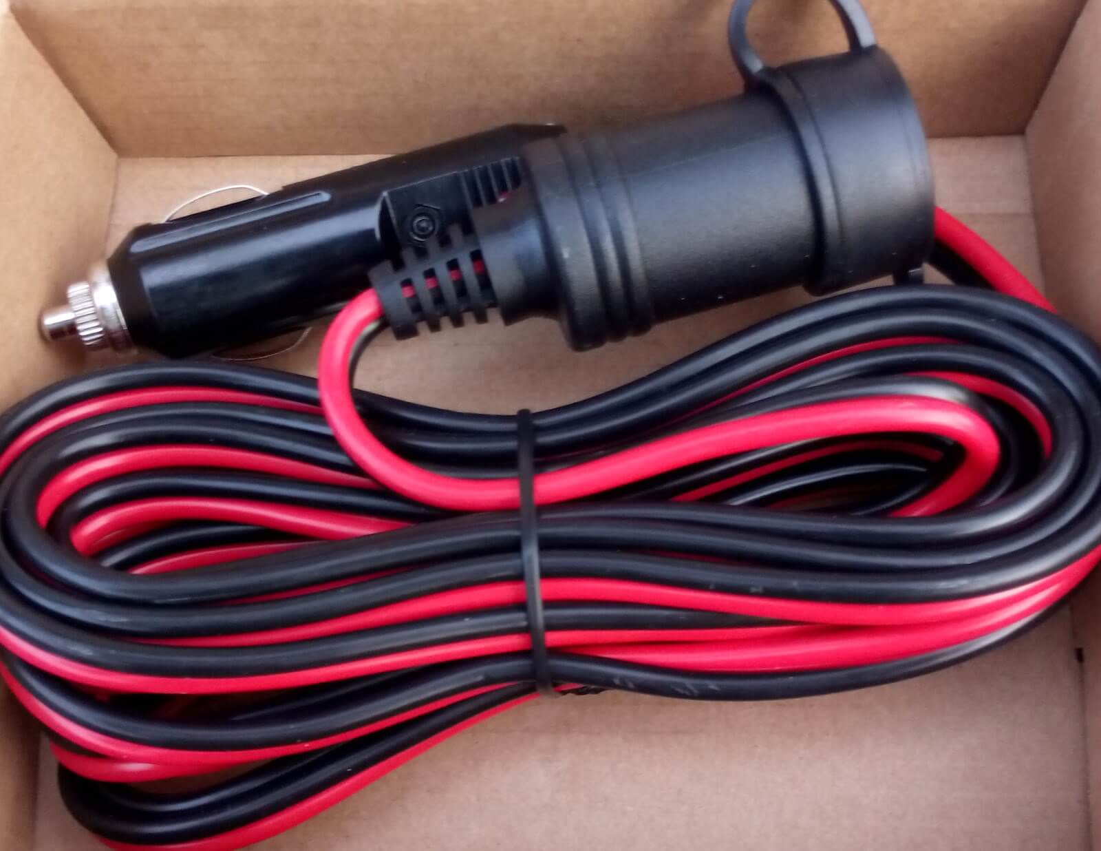
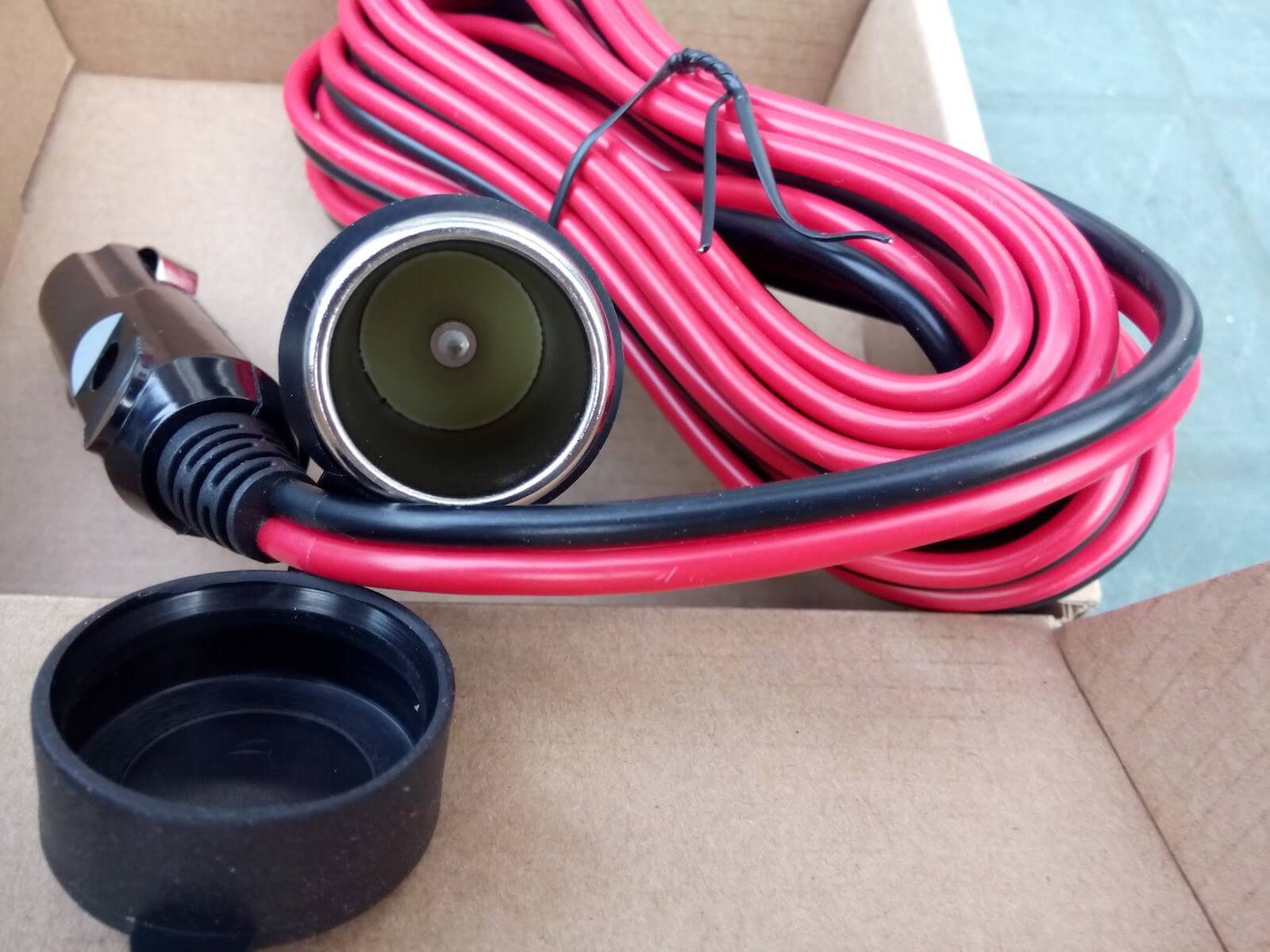
I also dug out my barely-used cheap 150W 12VDC to 240VAC 50Hz MSW inverter, plugged it in, and it does on the face of it seem to work, though the radio that I plugged into it was not very happy on MW.
: Target Hit 2018 Summer Solstice
See the battery activity for , ie the summer solstice. (There is a new grey line there, see below...)
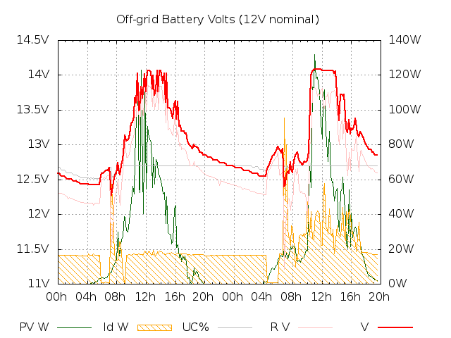
I now have more careful management of dump thresholds, based on an explicit SoC calculation including temperature and internal resistance compensation. The computed SoC is the grey line in the graph. It is positioned to match the 12.2–12.7V battery voltage that corresponds to the 0–100% usable charge that it approximately corresponds to.
I added the Google "gtest" unit-test framework to allow me to verify a couple of the key SoC calculations.
As a result I am able to better (safely) discharge and take the 'dump' load off-grid more (almost continuously). As a consequence the battery can then accept a decent charge the subsequent day.
I have also been powering my MacBook from the off-grid system almost entirely, when at home.
I may not have entirely trashed the batteries' capacity as I had feared. I may simply have been loading them over-cautiously.
: I think that the last time I plugged my laptop into mains power at home was back in June, so other than when I have been working elsewhere, all (50Wh+/d) of its energy has been off-grid.
: the heatwave has passed and we have near-normal British summer rain for now. I am moving my laptop back on-grid having beaten up the off-grid store today!
: Storage Interop
Towards the end of August (27th-) I tweaked the control algorithm to interoperate with the Enphase grid-tied storage (~1.1kWh) installed at the start of the month.
The intention was to better self-consume solar off-grid and grid-tied. So when the grid-tied system is spilling to grid, and the grid carbon intensity (or demand) is not too high, and the off-grid storage is not full, the off-grid system stops dumping to maximise charging, and retain that energy for later in the day.
That seems to be working nicely, effectively adding up to 100Wh (~10%) to the grid-tied storage capacity (80Wh or ~5h has been seen several times).
A good, unexpected, side effect has been letting the the off-grid storage charge faster and better, earlier. In fact, the storage has hit 'FULL' in the view of the Morningstar controller several times in the few days. Typically the gap between 'FULL' indications has been much longer even with much better insolation earlier in the year. Recent days where 'FULL' was hit at some point are:
20180601
20180602
20180603
20180605
20180606
20180607
20180608
20180609
20180610
20180611
20180613
20180615
20180621
20180627
20180628
20180629
20180630
20180701
20180703
20180801
20180830
20180901
20180902
20180903
: the battery may indeed be fading or I may have to tweak thresholds. Having been FULL up until about 4pm the previous day, the dump is dropping out after well under 200Wh dump-load discharge. That's <10% of nominal usable new-battery capacity, whereas even with my various conservative thresholds I should have four or five times that.
There seems to be a reporting bug too, since the grid-tie system seems to have been claiming to export briefly in the middle of the night...
2018/09/11T01:50:06Z AL 0 B1 12461 B2 -1 P 16387 BV 12046 ST OK - s A1P 0 B1T 20 UC 74
and:
20180911T01:49Z consumption.readingTime 1536630525 consumption.net.wNow -20.899 consumption.total.wNow -24.132 production.wNow -3.233 storage.percentFull 25 storage.wNow 83 storage.readingTime 1536630512
: Less Dumping
Since the networking fix, the router has not been available to be switched off-grid. Only minor loads such as the Loop network interface (~5W) have been available. I have been manually putting loads (especially my Mac, including running SETI@Home on it) off-grid, but the off-grid system is not getting pushed as hard as it otherwise might be.
That is lowering Wh/d collection (since energy has nowhere to go), I think.
: Performance Update
The target was to obtain ~500Wh/d off-grid. As of today the figure is maybe a little north of 100Wh/d. Note that there is not currently any dump load, which limits how much can be drawn from the solar controller load terminals. Some small loads such as AA NiMH charging, not visible in this view, are also being serviced from time to time.

: with the dump load reconnected, and a judicious amount of solar tea making, off-grid use is back over 300Wh/d at the moment. There is still unused PV energy based on observing raw PV input from the 550Wp array being allowed above Vmpp.
The implication of the ~10h support of a ~14W load after sunset (18h to 04h) to about 75% SoC (~55% usable capacity) is a full capacity ~600Wh. Nominal full capacity is 4*99Ah*12V ie 4800Wh, so capacity is down to ~1/8th original. After more than 10 years constant use, that is not too shabby. Overdue for replacement though.
: New Battery?
Yet again, I'm considering replacing my gel LA set now over 10 years old.
Read more about my battery bank replacement plans.
: 31V MPP

I think that A1V (primary array voltage) over 31V is a better indicator of unused energy (over Vmpp), especially when cool (~12°C) as today.
: as temperatures drop I think that ~32V is likely a better threshold. The data sheet lists Voc ~37.7V, Vmpp ~30.6V. I have updated scripts and graphing today to use 32V.
: Shading
Of the two big 255Wp panels ("primary array") facing due south, it is agreed that one will be kept unshaded at all times when possible. The other from a few days ago has a tall flowering plant starting to grow in front of it (the panel to the west that catches full sun earlier). So the total array expected generation will start later and be lower.
There's a similar situation elsewhere with an older amorphous panel (nominally ~40Wp) which for the summer is mainly hidden behind goldenrod and fuschia. But it gets to catch the winter sun in full. Because of this panel's vertical stripes it should still be contributing a little all year.
: Better Energy Capture

powermng algorithm seems to have done a better job of capturing and using PV generation this summer than the last two. Even with less good sunshine this than last year. Note ~3:1 summer:winter generation ratio cf ~10:1 for E-/W- facing grid-tie array on roof.: Cliff-edge Generation Rise
As the sun comes round side of house and 4 full vertical columns out of 6 are exposed to direct sunlight power rockets up from ~30W to ~60W in a few minutes...
This is a feature of the panels being shaded by the sun before solar noon. This effect diminishes towards mid-winter as the sun-arc across the sky gets narrower. Just when extra generation is most welcome, in fact.


Note low panel voltage (≤20V) while maximum power from the brightly-lit 2/3rds of one panel via bypass diodes is higher than from both full panels (≥27V).
% /usr/local/bin/powermng -nv
Verbose mode ($Id: powermng.cpp 41799 2021-09-16 15:07:57Z dhd $).
ISEXPPI=1: Expander Pi is in use.
LOAD POWER (mW): 14801
SS-MPPT-15L Vb_f slow battery voltage (mV): 13144
SS-MPPT-15L Adc_il_f load current (mA): 1126
Input flag DUMPING is set.
System dumping for 1589m.
SS-MPPT-15L Adc_ic_f battery charge current (mA): 2042
External flag file /var/log/SunnyBeam/LOW.flag is absent.
NET battery charge current (mA): 916
SS-MPPT-15L T_batt (C): 19, temperature compensation 15mV.
Estimated LA battery impedance: 87mohm.
Estimated LA battery sag/(-rise) from internal impedance, and nominal internal voltage, effective w/ temp comp: 79mV, 13065mV, 13050mV.
Estimated actual battery sag from load (mV): 0mV.
LA/B1 dynamic threshold adjustment for load current 0mV.
Battery voltage 1 local (LA) 12881mV.
Supply drop B1 to BV 263mV; implied supply impedance 233mohm.
Adc_vl_f load voltage (mV): 13157
Supply drop B1 to controller load terminals -13mV; implied controller impedance -11mohm.
Supply drop controller to BV 276mV; implied wiring impedance 245mohm.
Input flag EXTERNAL_BATTERY_NOTVHIGH is set.
Input flag EXTERNAL_BATTERY_NOTFULL is set.
Battery voltage 1 basic compensation 15mV.
Battery voltage 1 'very low' threshold 12215mV (raw 12200mV).
Battery voltage 1 'low' threshold 12465mV (raw 12450mV).
Battery voltage 1 dump margin threshold 12465mV (B1 delta 150mV, sag for dump load 112mV).
Battery voltage 1 'not high' threshold 13450mV (raw 13450mV).
Battery voltage 1 'very high' raw threshold 13600mV.
Input flag FORECAST_PV_GEN_GOOD is unset.
Battery extra USoC reserve for poor forecast / VHIGH and FULL not recent 5%.
Battery 1 effective/usable SoC 100%, dump thresholds min 60% higher 80% (uncompensated USoC 100%); usable to dump = 1.
Input flag NODUMP is unset.
External flag file /rw/docs-public/www.hd.org/Damon/Env/_gridCarbonIntensityGB.red.flag is absent.
Input flag GBGRIDPEAK is unset.
Dumping driven by external factors.
SS-MPPT-15L Power_out A1P (mW) 26951.
SS-MPPT-15L Adc_va_f array voltage (mV): 28330
LASTDATA: 2021/09/27T10:39:56Z AL 2042 B1 13144 B2 -1 P 14801 BV 12881 ST OK D e A1P 26951 B1T 19 UC 100 A1V 28330
% /usr/local/bin/powermng -nv
Verbose mode ($Id: powermng.cpp 41799 2021-09-16 15:07:57Z dhd $).
ISEXPPI=1: Expander Pi is in use.
LOAD POWER (mW): 16769
SS-MPPT-15L Vb_f slow battery voltage (mV): 13245
SS-MPPT-15L Adc_il_f load current (mA): 1266
Input flag DUMPING is set.
System dumping for 1590m.
SS-MPPT-15L Adc_ic_f battery charge current (mA): 4310
External flag file /var/log/SunnyBeam/LOW.flag is absent.
NET battery charge current (mA): 3044
SS-MPPT-15L T_batt (C): 19, temperature compensation 15mV.
Estimated LA battery impedance: 87mohm.
Estimated LA battery sag/(-rise) from internal impedance, and nominal internal voltage, effective w/ temp comp: 264mV, 12981mV, 12966mV.
Estimated actual battery sag from load (mV): 0mV.
LA/B1 dynamic threshold adjustment for load current 0mV.
Battery voltage 1 local (LA) 12065mV.
Supply drop B1 to BV 1180mV; implied supply impedance 932mohm.
Adc_vl_f load voltage (mV): 13318
Supply drop B1 to controller load terminals -73mV; implied controller impedance -57mohm.
Supply drop controller to BV 1253mV; implied wiring impedance 989mohm.
Input flag EXTERNAL_BATTERY_NOTVHIGH is set.
Input flag EXTERNAL_BATTERY_NOTFULL is set.
Battery voltage 1 basic compensation 15mV.
Battery voltage 1 'very low' threshold 12215mV (raw 12200mV).
Battery voltage 1 'low' threshold 12465mV (raw 12450mV).
Battery voltage 1 dump margin threshold 12465mV (B1 delta 150mV, sag for dump load 112mV).
Battery voltage 1 'not high' threshold 13450mV (raw 13450mV).
Battery voltage 1 'very high' raw threshold 13600mV.
Input flag FORECAST_PV_GEN_GOOD is unset.
Battery extra USoC reserve for poor forecast / VHIGH and FULL not recent 5%.
Battery 1 effective/usable SoC 100%, dump thresholds min 60% higher 80% (uncompensated USoC 100%); usable to dump = 1.
Input flag NODUMP is unset.
External flag file /rw/docs-public/www.hd.org/Damon/Env/_gridCarbonIntensityGB.red.flag is absent.
Input flag GBGRIDPEAK is unset.
Dumping driven by external factors.
SS-MPPT-15L Power_out A1P (mW) 57888.
SS-MPPT-15L Adc_va_f array voltage (mV): 20069
LASTDATA: 2021/09/27T10:41:02Z AL 4310 B1 13245 B2 -1 P 16769 BV 12065 ST OK D e A1P 57888 B1T 19 UC 100 A1V 20069
% /usr/local/bin/powermng -nv
Verbose mode ($Id: powermng.cpp 41799 2021-09-16 15:07:57Z dhd $).
ISEXPPI=1: Expander Pi is in use.
LOAD POWER (mW): 15856
SS-MPPT-15L Vb_f slow battery voltage (mV): 13257
SS-MPPT-15L Adc_il_f load current (mA): 1196
Input flag DUMPING is set.
System dumping for 1591m.
SS-MPPT-15L Adc_ic_f battery charge current (mA): 4491
External flag file /var/log/SunnyBeam/LOW.flag is absent.
NET battery charge current (mA): 3295
SS-MPPT-15L T_batt (C): 19, temperature compensation 15mV.
Estimated LA battery impedance: 87mohm.
Estimated LA battery sag/(-rise) from internal impedance, and nominal internal voltage, effective w/ temp comp: 286mV, 12971mV, 12956mV.
Estimated actual battery sag from load (mV): 0mV.
LA/B1 dynamic threshold adjustment for load current 0mV.
Battery voltage 1 local (LA) 12126mV.
Supply drop B1 to BV 1131mV; implied supply impedance 945mohm.
Adc_vl_f load voltage (mV): 13349
Supply drop B1 to controller load terminals -92mV; implied controller impedance -76mohm.
Supply drop controller to BV 1223mV; implied wiring impedance 1022mohm.
Input flag EXTERNAL_BATTERY_NOTVHIGH is set.
Input flag EXTERNAL_BATTERY_NOTFULL is set.
Battery voltage 1 basic compensation 15mV.
Battery voltage 1 'very low' threshold 12215mV (raw 12200mV).
Battery voltage 1 'low' threshold 12465mV (raw 12450mV).
Battery voltage 1 dump margin threshold 12465mV (B1 delta 150mV, sag for dump load 112mV).
Battery voltage 1 'not high' threshold 13450mV (raw 13450mV).
Battery voltage 1 'very high' raw threshold 13600mV.
Input flag FORECAST_PV_GEN_GOOD is unset.
Battery extra USoC reserve for poor forecast / VHIGH and FULL not recent 5%.
Battery 1 effective/usable SoC 100%, dump thresholds min 60% higher 80% (uncompensated USoC 100%); usable to dump = 1.
Input flag NODUMP is unset.
External flag file /rw/docs-public/www.hd.org/Damon/Env/_gridCarbonIntensityGB.red.flag is absent.
Input flag GBGRIDPEAK is unset.
Dumping driven by external factors.
SS-MPPT-15L Power_out A1P (mW) 60214.
SS-MPPT-15L Adc_va_f array voltage (mV): 20069
LASTDATA: 2021/09/27T10:41:08Z AL 4491 B1 13257 B2 -1 P 15856 BV 12126 ST OK D e A1P 60214 B1T 19 UC 100 A1V 20069
And from the normal logs:
2021/09/27T10:20:06Z AL 2254 B1 13114 B2 -1 P 14675 BV 12846 ST OK D e A1P 29684 B1T 19 UC 100 A1V 28278
2021/09/27T10:30:06Z AL 2225 B1 13178 B2 -1 P 14140 BV 12837 ST OK D e A1P 29186 B1T 19 UC 100 A1V 29059
2021/09/27T10:40:06Z AL 2629 B1 13151 B2 -1 P 15663 BV 12889 ST OK D e A1P 35014 B1T 19 UC 100 A1V 20948
2021/09/27T10:50:06Z AL 2334 B1 13233 B2 -1 P 16317 BV 12960 ST OK D e A1P 47787 B1T 19 UC 100 A1V 16837
2021/09/27T11:00:06Z AL 12997 B1 14158 B2 -1 P 24225 BV 13767 ST H D h A1P 183463 B1T 19 UC 100 A1V 27341
: 100Wp Mini Expansion

I have decided to put up my currently-unused 100Wp panel on the shed roof, wired into the PWM controller, for a little boost mid-winter. It will be more or less facing straight up but nominally south. I think that it will be well within the 20A maximum controller capacity. I have ordered cable and M4 connectors to that end. I will put a blocking diode in series to protect the panel. (The 100Wp panel is in a prime spot near the front with least shading.)
: 100Wp panel was connected to the PWM side via a Schottky blocking diode. Total PWM input ~200W from 2W+60W on west, 100W+20W+20W on east of house.
: a quick sample at close to (overcast) solar noon suggests that the 100Wp panel is adding ~5W (Isc ~400mA, V ~13V, diode drop ~0.3V). The 510Wp primary array is contributing a similar amount.
: Tweaking Parameters
The promise of legal UK plug-in solar arriving this year made me think about this again, with the prospect of maybe pulling ~0.5kWh/d in December from the existing primary off-grid array with more aggressive dumping/discharge to make space for more charging, and taking that load away from the grid. That could reduce grid imports by ~5% mid-winter. Load on the off-grid system would be reduced in summer to compensate, when there is plenty of excess grid-tied PV generation, to help maintain the overall life of the lead-acid battery,
Some of that shifted load would be taking the router off-grid all day (~288Wh), and some might be running my MacBook Air off-grid (up to ~150Wh), made more plausible with the help of a tuned USB supply.
(Actually adding a maxed-out plug-in solar system pointing due south might generate ~1kWh/d and reduce grid import by another ~10% mid-winter, and our FiT administrator will allow it.)
Making the battery hungry for charge is allowing this ~151W absorption:
2026/04/28T11:25:58Z AL 10560 B1 13926 B2 -1 P 27254 BV 12784 ST VH D c A1P 151077 B1T 17 UC 100 A1V 33503
: Refencing?
Our neighbours (to our south) are moving out and the fence between us is currently a tatty saggy wire mesh.
This is all a bit 'organic' for various reasons, but there are 2–4 spaces between concrete uprights of ~1400x1000mm that solar panels might go in.I might also replace the ancient 60W panel further down our garden side wall with one of these.
Bimble Solar's cheapest as of at £75 including VAT (but excluding delivery) each is 460W TCL Solar S-Class N-type Shingled Double Glass Bi-Facial (36Vmpp), ~22.7% panel conversion efficiency (460Wp, 1790x1134mm, 2.0m^2, ~230W/m^2), which would require a vertical fit between posts. Cf ~17.1% for the Sanyo HIT on the roof (215Wp, 1580x798mm, 1.3m^2, 170W/m^2), and ~15.9% for the CS6P-255P (255Wp, 1638x982mm, 1.6m^2, 160W/m^2) existing big panels on our garden side wall.
(Side note: ~10kWp ie ~21x at ~45m^2 of these 460Wp vertical panels with no shading or obstruction could likely carry our entire winter house load at >400kWh/month in Dec/Jan, ie including space heating, but many days' storage would be needed too. The implied ~10m-high fence might be unpopular!)
Those might be conceivably make some mixture of additional off-grid and 'grid-tied microinverter plug-in solar' capacity.
An alternative (lower power, much more expensive, possibly better look) is 175W Perlight Delta Mono Percium All Black (17Vmpp), at 1080x885mm (0.96m^2), so could go horizontally raised a from the ground. £119 including VAT excluding delivery at .
It might also be good to upgrade the PWM controller to something like the 30A Waterproof 12v-24v MPPT charge Controller - Tracer 7810CPN (£59 including VAT) which appears to be common negative rail, allowing freeing up one of my 4-way round the side of the house for plug-in, might also capture more from my existing rag-tag 12V panel set, and allow a little expansion there too?
A note from EPEVER technical support:
It is safe and allowed to share a common negative bus for all equipment. The internal common-negative design of Tracer 7810CPN supports sharing the negative line with other common-negative solar controllers, as long as you don’t parallel the PV positive, battery positive or load positive circuits of different controllers. Please kindly note that parallel charging operation of multiple controllers is still not supported, and any damage caused by parallel positives will not be covered by warranty.
Further communication established that:
... IT-NC/ET-NC/TEP G3 series MPPT controllers support parallel charging function. Multiple identical controllers can be connected in parallel to charge one battery bank via CAN communication cable for synchronous charging management.